Description
Στοιχεῖα is a dual Euclidean Sequencer. It algorithmically generates rhythmic sequences from an input trigger signal.
The name (Στοιχεῖα, Stoicheia, or Elements) comes from the title of Euclid’s book Elements in which the algorithm was first described.
History
This goes way back. In the third century BCE, the Greek mathematician Euclid described a way to determine the largest common denominator of any two integers. As it turns out, his method is the same as what people have used to divide beats into rhythms. Across the globe, from ancient to modern times; the rhythms that pervade human existence can be generated using the same, simple algorithm.
The cultural and historical range covered by these rhythms is nothing short of breathtaking. From Brazilian Samba and Bossa-Nova, to Bulgarian folk dances, thirteenth century Persian drum patterns, and complex poly-rhythms of West and Central Africa.
Of course, Euclid’s work can be applied to more than just rhythmic patterns. A scientist named Bjorklund applied it to nuclear physics, in order to optimise the operation of the SNS particle accelerator. He also published his work with a proof of the efficiency of his method. Then, in 2005, a Professor of Computer Science called Godfried Toussaint linked up the dots and presented in a research paper the connection between the work of Euclid, Bjorklund, and musical rhythms.
We have based our implementation on the work of Toussaint, Bjorklund and Euclid.
Getting Started
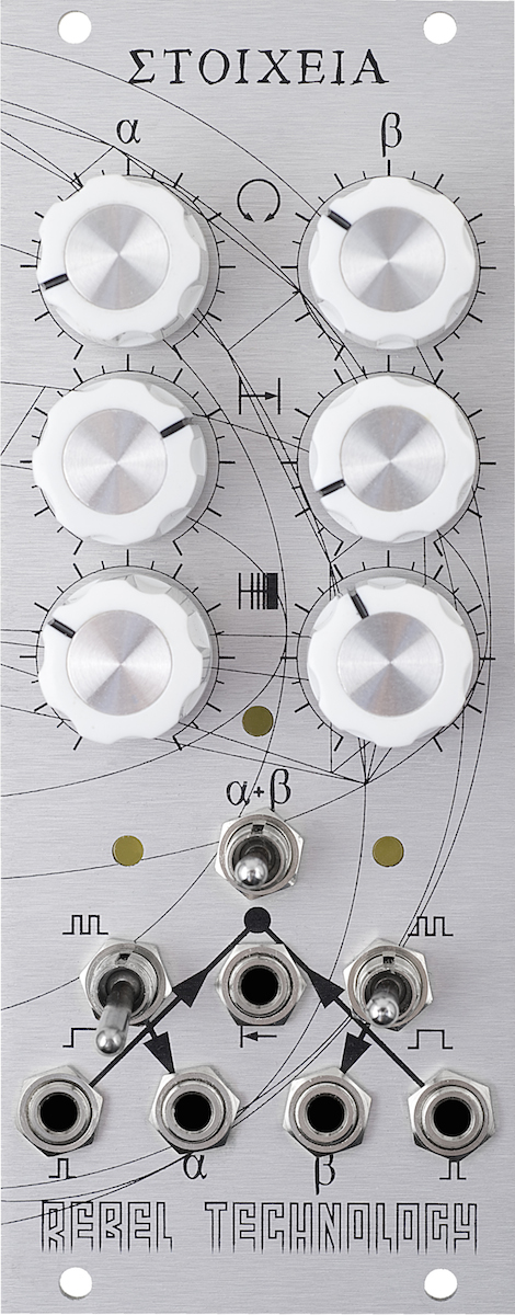
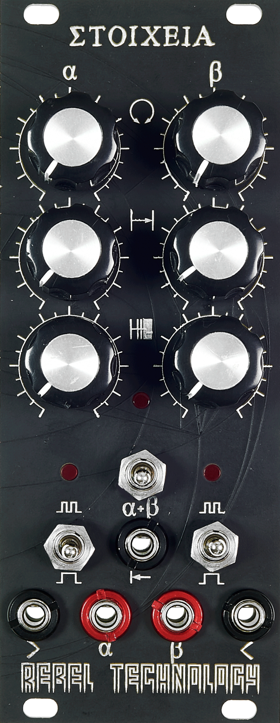
Connect the left sequence output (second jack from the bottom left) to an envelope gate input controlling a sound source, or something like the trigger input of a drum module.
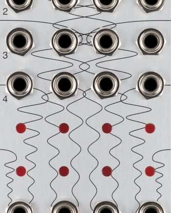
Make sure the middle switch is in the centre position, and the left switch is in the up position. Now connect an LFO to one of the two clock inputs (bottom left or bottom right jack) and you should see the centre LED light up when a signal is received. If the LFO is very fast, the LED will appear to be dimly on – turn the speed down (or up) to where it is flashing at a regular pace.
When an input clock signal is received, the centre LED will light up. When a sequence triggers an output gate signal, its corresponding LED will light up.
Turn all the knobs in the left column to their centre positions. You should know have a sequence of length 8 with 4 fills (50% of the step length). This means that every other beat will be ‘on’, and you should see the sequencer LED flash on every second input clock. Consequently, the sequence output should generate a gate signal, triggering the module you have connected it to.
If you turn the bottom left knob in the anti-clockwise direction, you will hear progressively fewer ‘on’ beats in the sequence until only one in 8 (the sequence length) beats is on. Turning in the clockwise direction, the sequence will start filling in more and more beats, until every beat is on.
Now connect a different envelope or sound source to the other sequence and repeat!
Instructions
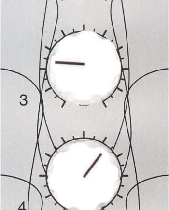
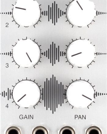
Each sequence is controlled by a column of three knobs and a switch. The input parameters to the algorithm are sequence length and fills.
The length of the sequence, measured in clocks or beats, is controlled by the second knob from the top. The range goes from 1 (fully counter clockwise) to 16 (fully clockwise), with 8 in the centre position.
The number of fills, or on-beats, is set by the third knob. In fully counter-clockwise position, this is set to 1. Centre position will set every other beat ‘on’, or 50% . Fully clockwise sets every beat ‘on’, in other words: the number of fills are equal to the sequence length.
The top knob adjusts which beat the sequence starts on – and hence resets to. In its centre position, the sequence will start on its first step. The start position can be changed by turning the top knob left or right: this will have the effect of rotating the sequence left or right, respectively.
Trigger Mode
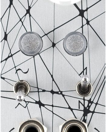
With its switch in the centre position, the sequence is turned off. To turn it on (Trigger Mode), push the switch up. In trigger mode, the sequence will switch its output high when receiving a clock signal rising edge (low to high transition), provided the next beat in the sequence is ‘on’. When the clock signal falling edge is received (high to low transition), the output will be switched back to low (0v). This means that the output trigger signals have the same pulse width as the input clock. So if the clocks are generated with very short pulses, the output triggers will be equally short. As a consequence, a pulse width modulation on the input clock signal will be passed on through the sequencer.
Alternating Mode
Pushing the switch down from its centre (off) position puts the sequence into Alternating Mode. In alternating mode, the output goes high on the first ‘on’ beat, and remains high until the next ‘on’ beat. In other words, the output toggles on every ‘on’ beat in the sequence. The up and down transitions occur on the rising edge of the input clock.
Reset
The centre jack can be used to connect a reset trigger. When a reset is received, both sequences restart at their first position. This takes into consideration the rotation setting: If sequence A and B have different rotations, they will remain offset in respect to each other. Reset can also be manually triggered by pushing the centre switch momentarily upwards.
Chained Mode
The centre switch can be pushed down, which enables Chained mode. When chained, the two sequences are repeated one after the other, instead of concurrently. This is very useful to build up more complex patterns. In chained mode, the output of the combined sequence is available at both output jacks. On startup, the first sequence will play through to its determined length. It will then stop, and the second sequence will play through to the end, at which point the first one starts up again. For example, setting the first sequence to length 12, and the second to length 4, will result in a combined 16-step sequence. A reset signal in Chained mode brings the combined sequence to the start of the first pattern. Rotation works as in regular mode. Chained mode can also be used to create sequences longer than 16 steps.
Patterns
A simple beat sequence can be written as a combination of dots and crosses. For example ...x...x would mean a sequence of 8 steps, with two on-beats. Furthermore, we can write the corresponding Euclidean pattern concisely as E(2,8). This simply means 8 steps with 2 fills; the exact distribution will be determined by the Euclidean algorithm. With this, we can write out what some of those patterns are:
| Setting | Pattern | Description |
| E(3,4) | [x . x x] | Calypso rhythm from Trinidad |
| E(2,5) | [x . x . .] | Metric pattern of the second movement of Tchaikovsky’s Symphony No. 6, and of Dave Brubeck’s Take Five |
| E(5,8) | [x . x x . x x .] | Cuban cinquillo pattern. When started on the second onset it is also the Spanish Tango, and a thirteenth century Persian rhythm, the Al-saghil- al-sani |
| E(7,12) | [x.xx.x.xx.x.] | Widespread pattern used frequently and with different onsets in Central and West African music. In Cuba it is the bell pattern of the Sarabanda rhythm associated with the Palo Monte cult |
| E(9,16) | [x.xx.x.x.xx.x.x.] | A rhythm necklace used in the Central African Republic. When it is started on the fourth onset it is a rhythm played in West and Central Africa, as well as a cow-bell pattern in the Brazilian samba. |
(As described by Godfried T. Toussaint in this brilliant paper)
Hacking
Στοιχεῖα is driven by a micro controller which interfaces modular signal levels through discrete transistor networks. It functions by responding to incoming trigger signals using the MCU’s built in hardware interrupts. The step sequences are pre-calculated in the main processor loop and updated when the knobs are turned, which means that the interrupts can be processed very efficiently. This leads to a very low on/off latency.
Efficient design, solid code and good use of hardware interrupts means that Stoicheia can process clock signals well into audible frequencies.
The circuit board has a 6-pin header which brings out the serial and reset pins of the MCU. It mates with an FTDI USB TTL Serial Cable. It is compatible with 3.3v and 5v TTL levels.
The MCU is an AVR ATMega168. It is loaded with the Arduino Bootloader, and can be programmed as an Arduino Diecimila. The firmware is dependent only on avr-gcc, and on Arduino/Wiring for the optional serial debug interface.
Specifications
Dimensions
- Height: 3U / 128.50mm
- Width: 10HP / 50.50mm
- Depth: 20mm
- Weight: 135g
Power
- 16-pin Doepfer/Eurorack
- Requires +5v
- PTC fuse and diode protected
- +12v: < 10mA
- -12v: 0mA
- +5v: < 25mA
Impedance
- Outputs: < 1.1k
- Inputs: > 100k
Voltage Range
- Output low: 0v
- Output high: 5.1v
Open Hardware

Στοιχεῖα is Open Source and Open Hardware, published under the Gnu GPL.
All source code is publicly available on github.
Please send your patches to us as pull requests on github.
The latest version of the circuit diagram is always here.

Johnny Fraglerock –
Bomb! Total bomb. Had it for a month. Playing with it constantly.
If you guys ever go for a v2 I would pay good money again to have CV control over the 6 knobs.
Love from Montreal
Y.